Insert Balloon
Place Balloons for Symbols included in referenced files
 Places a numbered balloon beside
a symbol in a drawing that indicates the position of that component in the Bill
of Materials list.
Places a numbered balloon beside
a symbol in a drawing that indicates the position of that component in the Bill
of Materials list.
Accessed from:
Balloon placement is supported for:
- Symbols included in referenced files. This includes symbols which are part saved views.
- Symbols placed in active page.
-
Selected items from BOM Manager . Selected items can include devices with or without symbols. Typically, devices without placed symbols are used to capture miscellaneous hardware ; such as, nuts, bolts, washers, etc. and these items are not directly associated to a placed symbol.
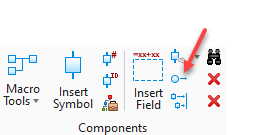
Step 1: Select Insert Balloon command.
Step 2: Select a symbol which is part of a saved view or reference file.
Step 3: Make appropriate selections in the Place Balloon dialog. Then proceed to place Balloon graphics.
Step 1: Select Insert Balloon command
Step 2: Select a symbol on active page. (does not apply if command is initiated from the Context menu)
Step 3: Make appropriate selections in the Place Balloon dialog. Then proceed to place Balloon graphics.
Step 1: Select desired items within BOM Manager.
Step 2: Select Insert Balloon command within BOM Manager dialog.
Step 3: Make appropriate selections in the Place Balloon dialog. Then proceed to place Balloon graphics.
Below example will result in four unique balloon groups:

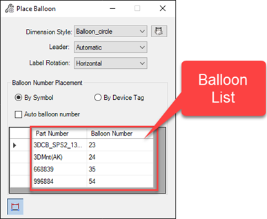
This dialog appears when using the Insert Balloon command. All balloon numbers and their respective part numbers for the active device or symbol are displayed in the "Balloon List". The Balloon list supports multiple selection using Ctrl and Shift key functions. The selected Balloon Numbers become available for placement.
| Setting | Description |
|---|---|
| Dimension Style |
Select the type of balloon to insert from the drop down. These balloon styles are defined in the Dimension Styles dialog. Balloon_Circle Balloon_Hexagon Balloon_Capsule Balloon_Line Balloon_circle without a leader Click the Dimension Styles icon
|
| Leader |
Select from the options below: Automatic: This option behaves like a typical leader line where there is an anchor point on the selected symbol and you can drag the balloon type to a location and left-click to place the balloon. Manual: This option lets you select multiple points for the leader creating segments for the line and allowing more flexibility to position the balloon. Once you are finished routing the leader line you must right-click to accept the final point. See the differences below: |
| Label Rotation |
Used to rotate balloon label as horizontal or vertical. |
| Auto balloon number |
When enabled, will automatically assign the next available balloon number. If disabled, you will be prompted to enter a balloon number manually. |
| Part Number | Displays the accessory kit part numbers as well as the kit parts themselves. |
| By Device Tag |
This allows you to associate a balloon to a device and not a symbol. This gives you more flexibility on where you can place balloons. When you select this option, the BOM Manager is opened where you can select which device to associate the balloon to. If multiple device tags are in the drawing associated with the same balloon number, then you will be prompted to place a separate balloon (with the same number) for each device in the drawing. |
| Balloon Number | Enter the desired balloon number in this field if the Auto balloon number option has been disabled. |
| Create association to symbol | Enable this button to create an association between the balloon and the symbol. When this is done if the symbol is moved in the drawing the balloon will be moved with it. |
 to display the Dimension Styles
dialog where you can edit the properties of the balloon types.
to display the Dimension Styles
dialog where you can edit the properties of the balloon types.
The software will prompt you to Pick leader start or balloon insert point. Click on the point where you wish the head of the arrow from the balloon to appear. Click where you wish the other end of the leader from the balloon to end. You can click on multiple points to create segments in the leader. If you wish the balloon to appear with no leader, simply press <Enter> , do not define any additional points.

Below items in Blue have been selected using Ctrl key.

Example Result:

As mentioned above, Dimension Styles set various properties controlling the graphical display balloons. Refer to Project Options Balloon Settings dialog for additional balloon settings.
Related to how to topics.
To Assign a Balloon Number in Device Propertie s Dialog
To Change or Automatically Renumber a group of Balloons in BOM Manager>Edit Dialog